
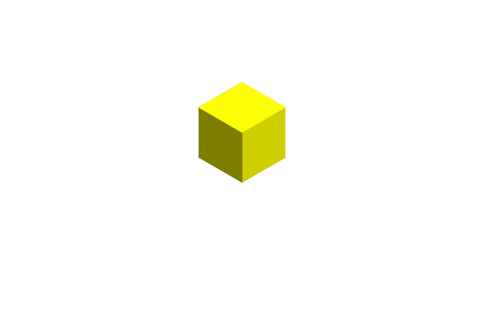
Isometric drawing is way of presenting designs/drawings in three dimensions. In order for a design to appear three dimensional, a 30 degree angle is applied to its sides. The cube opposite, has been drawn in isometric projection.

What is purpose of isometric design Android?
- You can use it for game development where you want to create 3D drawing.
- Blueprint of any house or 3D model.
- Small application for learner kids and many more what your thinking can do.
Lets come with implementing the isometric design Android library.
Include in your project
Using JCenter
compile 'io.fabianterhorst:Isometric:0.0.6'
Available Shapes
Cylinder

Knot

Octahedron
Prism
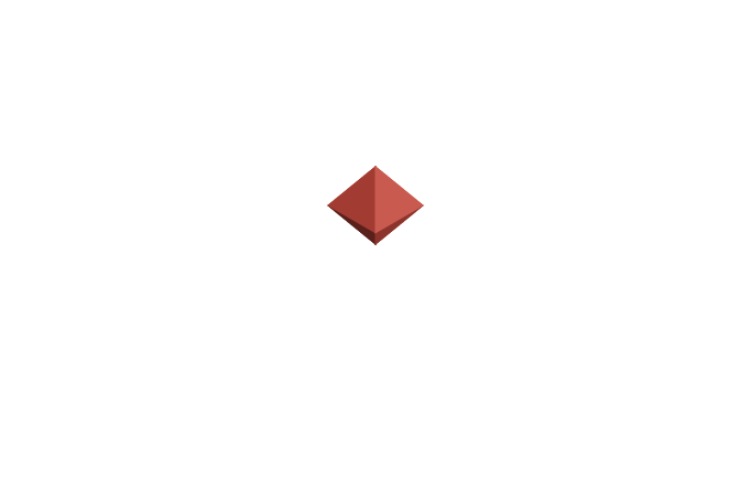
Pyramid

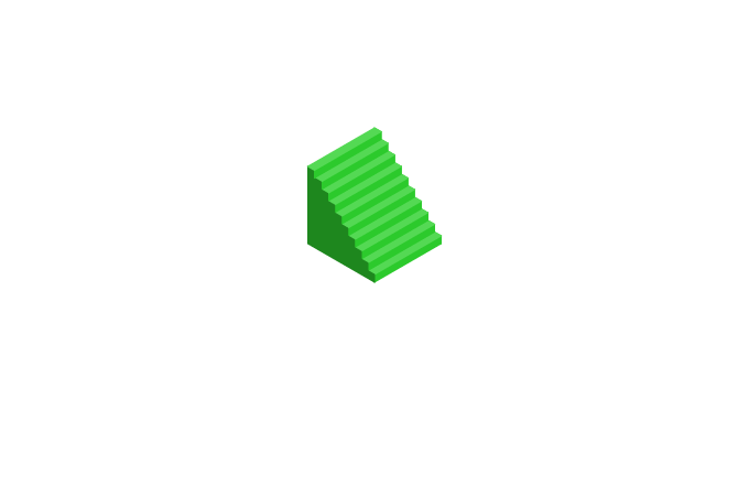
Stairs
Translate
Traslate is translating an point, path or shape to the given x, y and z distance. Translate is returning a new point, path or shape.
Prism prism = new Prism(new Point(0, 0, 0));
isometricView.add(prism, new Color(33, 150, 243));
isometricView.add(prism.translate(0, 0, 1.1), new Color(33, 150, 243));

Scale
Scale is scaling an point, path or shape with the given x, y and z scaling factors. Scale is returning a new point, path or shape.
Color blue = new Color(50, 60, 160);
Color red = new Color(160, 60, 50);
Prism cube = new Prism(Point.ORIGIN);
isometricView.add(cube.scale(Point.ORIGIN, 3.0, 3.0, 0.5), red);
isometricView.add(cube
  .scale(Point.ORIGIN, 3.0, 3.0, 0.5)
  .translate(0, 0, 0.6), blue);

RotateZ
RotateZ is rotating an point, path or shape with the given angle in radians on the xy-plane (where an angle of 0 runs along the position x-axis). RotateZ is returning a new point, path or shape.
Color blue = new Color(50, 60, 160);
Color red = new Color(160, 60, 50);
Prism cube = new Prism(Point.ORIGIN, 3, 3, 1);
isometricView.add(cube, red);
isometricView.add(cube
  /* (1.5, 1.5) is the center of the prism */
  .rotateZ(new Point(1.5, 1.5, 0), Math.PI / 12)
  .translate(0, 0, 1.1), blue);

Shapes from Paths
The method Shape.extrude allows you to create a 3D model by popping out a 2D path along the z-axis.
Color blue = new Color(50, 60, 160);
Color red = new Color(160, 60, 50);
isometricView.add(new Prism(Point.ORIGIN, 3, 3, 1), blue);
isometricView.add(Shape.extrude(new Path(new Point[]{
  new Point(1, 1, 1),
  new Point(2, 1, 1),
  new Point(2, 3, 1)
}), 0.3), red);

Drawing multiple Shapes
There are 3 basic components: points, paths and shapes. A shape needs an origin point and 3 measurements for the x, y and z axes. The default Prism constructor is setting all measurements to 1.
isometricView.add(new Prism(new Point(0, 0, 0)), new Color(33, 150, 243));
isometricView.add(new Prism(new Point(-1, 1, 0), 1, 2, 1), new Color(33, 150, 243));
isometricView.add(new Prism(new Point(1, -1, 0), 2, 1, 1), new Color(33, 150, 243));

Drawing multiple Paths
Paths are two dimensional. You can draw and color paths the same as shapes.
isometricView.add(new Prism(Point.ORIGIN, 3, 3, 1), new Color(50, 60, 160));
isometricView.add(new Path(new Point[]{
    new Point(1, 1, 1),
    new Point(2, 1, 1),
    new Point(2, 2, 1),
    new Point(1, 2, 1)
}), new Color(50, 160, 60));

The grid
Here you can see how the grid looks like. The blue grid is the xy-plane. The z-line is the z-axis.

Supports complex structures

Download Project
Have you tried this library ever? If no then use this cool library.
Share your thoughts